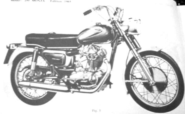
1965 Ducati 250 Monza(Specs directly from shop manual omitting
unneeded information)
Engine
4 Stroke
Single-cylinder, inclined 10 degrees, made of light alloy,
deeply finned; special cast iron inserted
liner.
Cylinder head: made of light alloy; hemispherical combustion chamber; inserted valve seats.
Bore: 74mm
Stroke: 57.8mm
Cubic capacity: 248.589cc
Compression Ratio: 8:1
Timing: by O.H.C., valves inclined 80 degrees.
Max output RPM: 7200
Carburetor: Dell’Orto UBF 24 BS with quiet air inlet in the toolbox.
Cooling: by air.
Lubrication: forced- by gear pump. Oil sump in crankcase.
Transmission: from engine to gearbox, by gears; from gearbox to wheel, by chain with special cushion drive.
Gearbox: in unit with engine; 4 speeds; constant mesh gears; pedal control with pre-selector.
Clutch: multi plate type running in oil bath.
~ ~
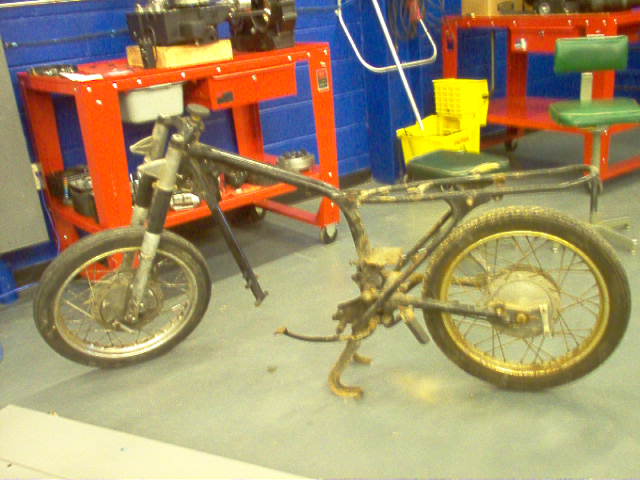
The Stripped Frame of the Ducati 250.
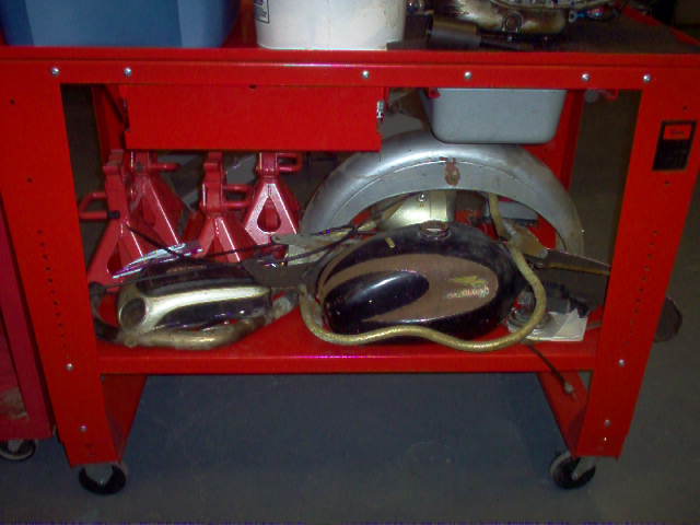
The pile of parts once the frame was stripped.
Before we even started the disassembly procedure, we sat down and skimmed through the shop manual that we were given. This gave us an idea of how the disassembly procedure should go. We weren’t that lucky to be able to follow it directly step by step, so we ended up skipping around a little bit, as we didn’t have some of the special tools that were recommended in the manual. We were able to bypass most of the tools without a problem, except for the flywheel puller which ended up having to be ordered.
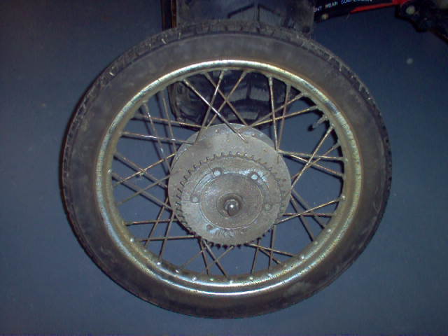
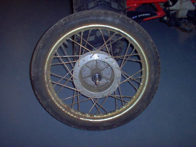
At the same time that we were working on the motor, in frames and suspensions lab, we brought the tires in, and broke them down off the wheels. For the tires and wheels being as old as they are, they were in pretty decent shape. The tires were discarded appropriately, as well as the inner tubes, which, one of the two were still intact (very surprising).
These were the measurements taken:
Original wheel size 19”
Spoke count 36
Rear Wheel measurements
Wheel off set 1.314” 1.330”
-measured from axle hub to edge with cushion drive rubbers
removed
Axle Runout .004”
Front Wheel measurements
Wheel off set (zero offset) .351” .368”
-measured from axle hub to edge
Axle Runout .001”
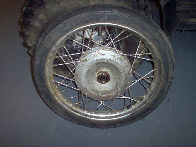
We looked up the information on replacing the wheels and spokes
at the same point due to their condition, as we needed the wheels and spokes in such a small time frame, we chose to replace them with new parts instead.
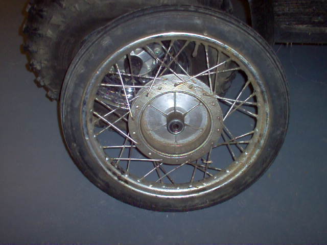
The original Ducati wheels before disassembly.
Engine Disassembly
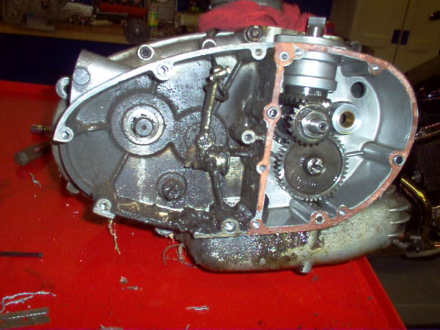
One section of the outer case was removed prior to us disassembling it, so we simply took our time removing outer pieces, which obviously needed to go before the case was split in half. While removing pieces, they were being cleaned at the same time in the parts tank, so that they could be bagged and tagged correctly, to facilitate reassembly.
We also took the time to scrape the old gaskets off from each piece, to ensure that it was not forgotten, as it is easier to simply use a razorblade to remove them than to soak them in the parts tank. Note the condition of the awesome helical bevel gears that are one of the unique features of this engine.
How dirty the engine was when the outer platers were initially taken off.
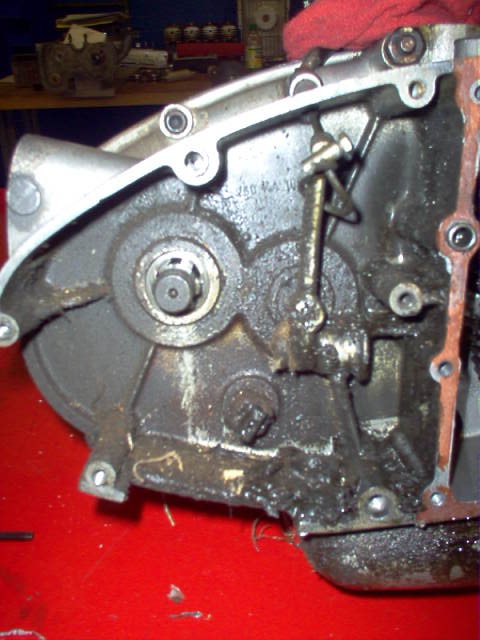
The dirtiest side of the engine.
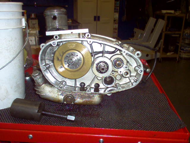
The flywheel side of the engine, (Note:for the age of it, the cleanliness is amazing) before the engine was split. (Note: the Polaris special tool being used to hold the piston from being damaged.
Both the cylinder and head were removed, but the piston was left on the crankshaft rod, as there was no justification to remove it. The head was torn down about a week later, and since we didn’t have the special tools needed to remove the valve springs, we wanted to take our time so that nothing was damaged. In order to remove them, we used two long handled scrapers to carefully press
down on the springs simultaneously, so that the center spring attachment could be removed. We were able to complete this without damaging any parts. The valves were in good shape, only
showing a small amount of scratching and pitting, however they are
being replaced so the precision measurements were not needed. The valve guides, made of copper, were in excellent shape as well, but due to the way that one valve came out, it suffered some minor damage, and rather than to take the chance, we are going to replace it appropriately. Once the cylinder was cleaned in the parts tank, the measurements were taken to determine whether or not the
cylinder was good. It was noted that there was a broken fin on the
cylinder, and it is going to be welded back on before the engine is
reassembled. The following measurements were taken on the
cylinder and piston:
Cylinder
Top x-axis 2.916”/74.07mm y-axis 2.916”/74.07mm
Middle x-axis 2.9155”/74.05mm y-axis 2.9155”/74.05mm
Bottom x-axis 2.914”/74.01mm y-axis 2.914”/74.01mm
Piston
X-axis 2.913”/73.99mm y-axis 2.907”/73.83mm
~ ~
The next step after removing the cylinder and head was to split the case. Before attempting this we made sure that all the bolts and
miscellaneous plates and screws were removed to facilitate this. We chose to leave the flywheel in place, since we didn’t have the tool to remove it appropriately and knew it wouldn’t be damaged by simply leaving it in place. Using long handled scrapers very carefully, so we wouldn’t ruin the sealing sides, we split the case.
Once split we found something rather amazing, the case seal, (we were assuming it was the original) was completely intact, made of a wax injected paper type material. We washed this off in the parts tank, and dried it to make sure we had it in case we couldn’t
find a replacement; we would be able to cut a new one out of
gasket material to substitute in place of the old one. All of the old bearings would be pressed out soon as well, since new ones were going to be ordered from Syd’s Cycles.
We learned from trial and error that there wasn’t any way to
could remove the flywheel without the special puller manufactured
by Ducati as there were threads on the flywheel that the manufacturer specific puller needed to attach to. We made several attempts with various other methods, the Snap-On
puller, just pulling on it, Snap-On crow’s feet under the edges and
applying pressure, and of course, we attempted to match up a
Polaris flywheel puller to it. We came very close with one, as it was only approximately 1/16” too small to fit. So we located the part number from the book, and attempted to order one. However, since it was on back order, Syd’s Cycles loaned his tool to us for a reasonable fee of $10.00. This saved us time, as we were able to immediately disassemble rather than having to wait until the puller arrived, which was approximately one week before our project was scheduled to be finished.
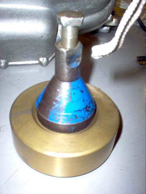
The flywheel puller shown on the flywheel after successfully removing it from the engine.
Once the flywheel was removed, both it and the stator were checked for damage. The flywheel was in excellent shape, it
just needed a good cleaning; however the stator had a wire that had come loose from the cold solder point, so it needed to be removed
immediately so that it could be sent out for repairs. It was sent to Syd’s in the hopes that it could be repaired, as we weren’t expecting to locate a replacement on such a short time frame. Syd’s came through for us though, as a phone call made on 12/1 gave us the good news that it was repaired, and bench tested, and we would be receiving it soon, as it had been shipped with our valves and valve guides.
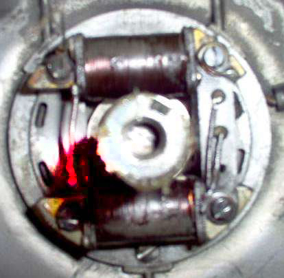
The broken wire on the stator assembly (area highlighted by the pink glow)
Once the flywheel, stator and crankshaft were removed, it was time to tape off the cases for bead blasting. We were hoping that by taking the time to bead blast, it would make the case halves look like they were just manufactured at the company. To prep the
cases properly with duct tape, it took us approximately 45 minutes. We had to ensure that all threaded holes, oil inlets, and openings were properly sealed off, as the glass beads could damage important engine components if not done correctly.
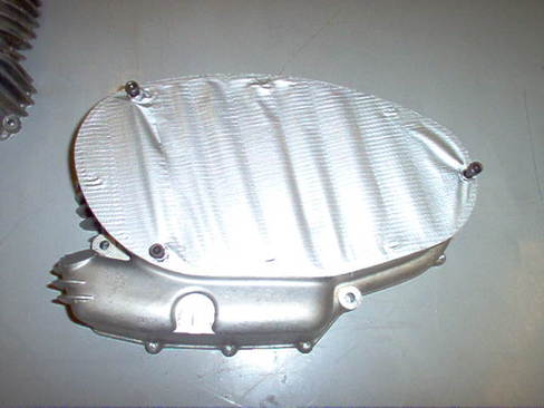
The cases taped up before bead blasting.
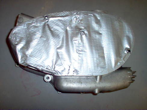
The cases taped up before bead blasting.
Once they were bead blasted, the tape was removed, and the cases then needed to be cleaned out, as the fine glass beads tend to get into everything, including the two bearings that were left in (they were masked to prevent direct damage, but it is impossible to have them air tight, as some beads in it is expected, and therefore needed to be cleaned very well). There was still a lot of work ahead
though, as the cases needed to be washed out several times, and after that, they needed to be scrubbed and polished with a wire brush to give it the look that was needed, and this
took us several hours to complete.
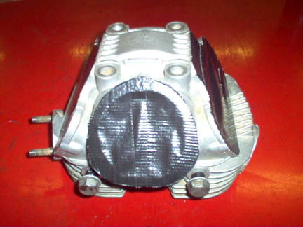
Once that was accomplished, the head now needed the same treatment as the case halves. This time however, the head didn’t need to be taped off as we wanted everything to be cleaned up to
some degree, especially the combustion chamber, which had large carbon deposits in it (We attempted to tape it off, and soon learned that it was simply pointless because there were so many different areas that we couldn’t effectively block off). By blasting the whole
thing, it cleaned up all the small areas where the valves and springs
went, as well as the chamber and the outside face of it. This alone was a significant reason for us to bead blast it as we wanted it to look the same as the rest of the engine that we had taken the time to bead blast and polish.
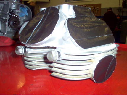
The head prior to being bead blasted. We soon learned after attempting to tape that it was futile, so it was removed after it went inside the cabinet.
Gearing Setup
This is a four speed, and the fourth gear is actually considered
overdrive, as it has one more tooth on the drive gear than the driven gear. We calculated the following numbers using this
formula:
Driven = gear ratio
Drive
Input ratio x Speed ratio x Output ratio = final gearing ratio
Input Ratio Output Ratio
60/24 = 2.5:1 47/16=2.6:1
Drive Gears Driven Gears
1st gear: 16 teeth 1st gear: 44 teeth
2nd gear: 23 teeth 2nd gear: 38 teeth
3rd gear: 28 teeth 3rd gear: 33 teeth
4th gear: 31 teeth 4th gear: 30 teeth
To figure out initial gear ratio:
1st: 44/16 = 2.75:1
2nd: 38/23 = 1.652:1
3rd: 33/28 = 1.1785:1
4th: 30/31 = .9677:1
Final Gearing Ratios
1st: 2.5 x 2.75 x 2.6 = 17.875:1
2nd: 2.5 x 1.652 x 2.6 = 10.738:1
3rd: 2.5 x 1.1785 x 2.6 = 7.66:1
4th: 2.5 x .9677 x 2.6 = 6.29005:1
Reassembly
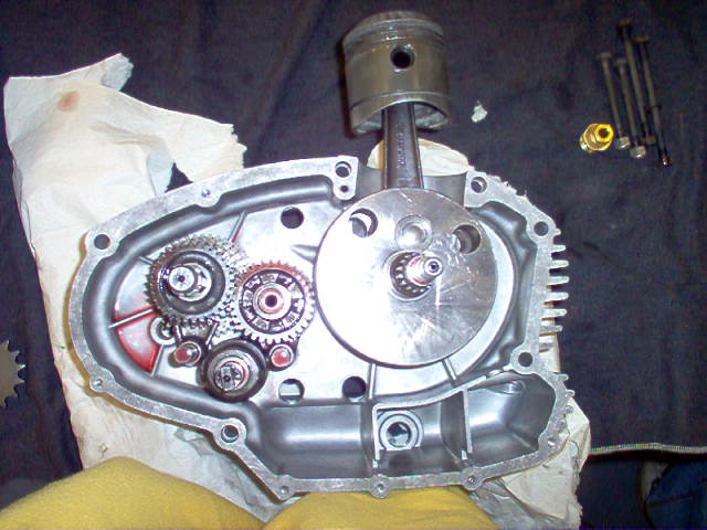
So far, we have the gears and the shift drum reinstalled in this half of the case (the red seen in the picture is reassembly lube)
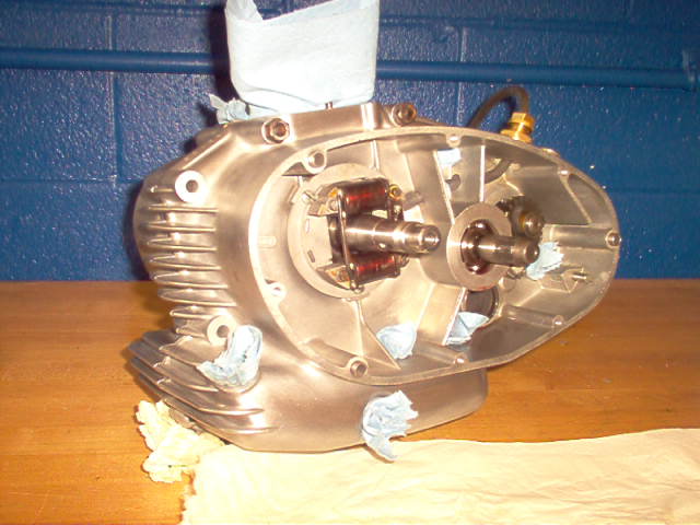
Photographed on the next page is the both halves properly put
together, the refurbished stator installed (we also installed the flywheel after this photo was taken) and the gearing. We then
moved on, installing the shifter, the kick start mechanism, and
the other miscellaneous pieces that belonged in the right section of the case side shown. After finishing this, we actually did fit the
cylinder on to see how it looked (the camera wasn’t handy at that
point, so we don’t have a picture of it mocked up) but didn’t have
the head, so we didn’t proceed any farther that day.
Later on, once we received the head from Leahy’s, as well as the book, we could start on some more of the engine. We checked the
ring end gap, as the packet of rings that we purchased for the project said file to suit, so we
needed to make sure that we did it properly the first time. Also, we chose to fit the valves in their new guides. We noticed, however, before proceeding, that the valve shaft had a very sharp edge, and we were worried about it possibly damaging the new guides that were installed. So Mr. Hill assisted us in fixing this problem, shown in the picture below.
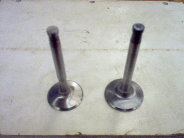
Left to right: Finished Intake Valve, unfinished Exhaust Valve.
